What are CAB gaps and how do they affect design?
There are many ways to handle the electrical design on a given project. Although the electrical engineer has the final say, RPCS does like to be involved in the process to make sure we provide a mechanical design that fits the needs of the electrical concept. How a customer chooses to electrically design their project can have significant effects on cost and structural design, and one of the most common examples comes in the form of “center gaps” when our customer uses the CAB above-ground wiring technique for cable management.
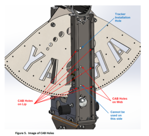
Array’s center structure comes prefabricated to work elegantly with the CAB above-ground wiring system. Mounting holes for the CAB L-brackets come standard on each center structure and give a variety of height options to the customer as seen in the figure below. Depending on the L-bracket’s size, the height at which the customer intends to mount, and the tracker block’s driveline angle, RPCS may require the use of a center gap in order to avoid interference with the mounted modules.

Mounting holes on the Array center structure.
Center gaps can vary in size, but they often end up around 36” total in order to avoid instances of interference. It is worth noting that center gaps do naturally add to the overall length of the module row by approximately the size of the empty space that they create. Because of this, it is wise to consider early on which method for wiring might be used for your project. This will ensure that all design documents line up with each other and result in a smooth/speedy material procurement process (as well as to avoid any on-site surprises down the road).
The angle of driveline/array block in a project can be one of the biggest factors in center gap sizes: the steeper the angle, the wider the center gap must be in order to keep the tracking modules out of the way of the CAB messenger wire. Because of this, it is important to note any changes to the layout footprint, module dimensions, or any other changes in project design to RPCS immediately after they are decided upon to allow RPCS to adjust their structural design accordingly.
At a certain point, it may become more practical to simply use lower CAB mounting methods in order to avoid the possibility of impacts altogether. Having all of these options can be very confusing to tackle by oneself, so that is where RPCS can help alleviate the burden by recommending our best options to the customer/electrical engineer and showing the resulting design characteristics early on to make the best decision possible. One major key to successful projects is communication, and RPCS provides a level of communication and workability that sets us apart from our competitors by keeping our customers in the know while simultaneously giving them the best single-axis tracker on the market.

Photo of an RPCS-build site in New Mexico, illustrating the CAB gap for above-ground wire management.
Have an engineering question? Ask Paul!
Submit your queries to info@rpcs.com for a chance to
have your question answered in future segments.